
New controls for a 2001 SyncroFlo pump station at Bootleg Gap Golf
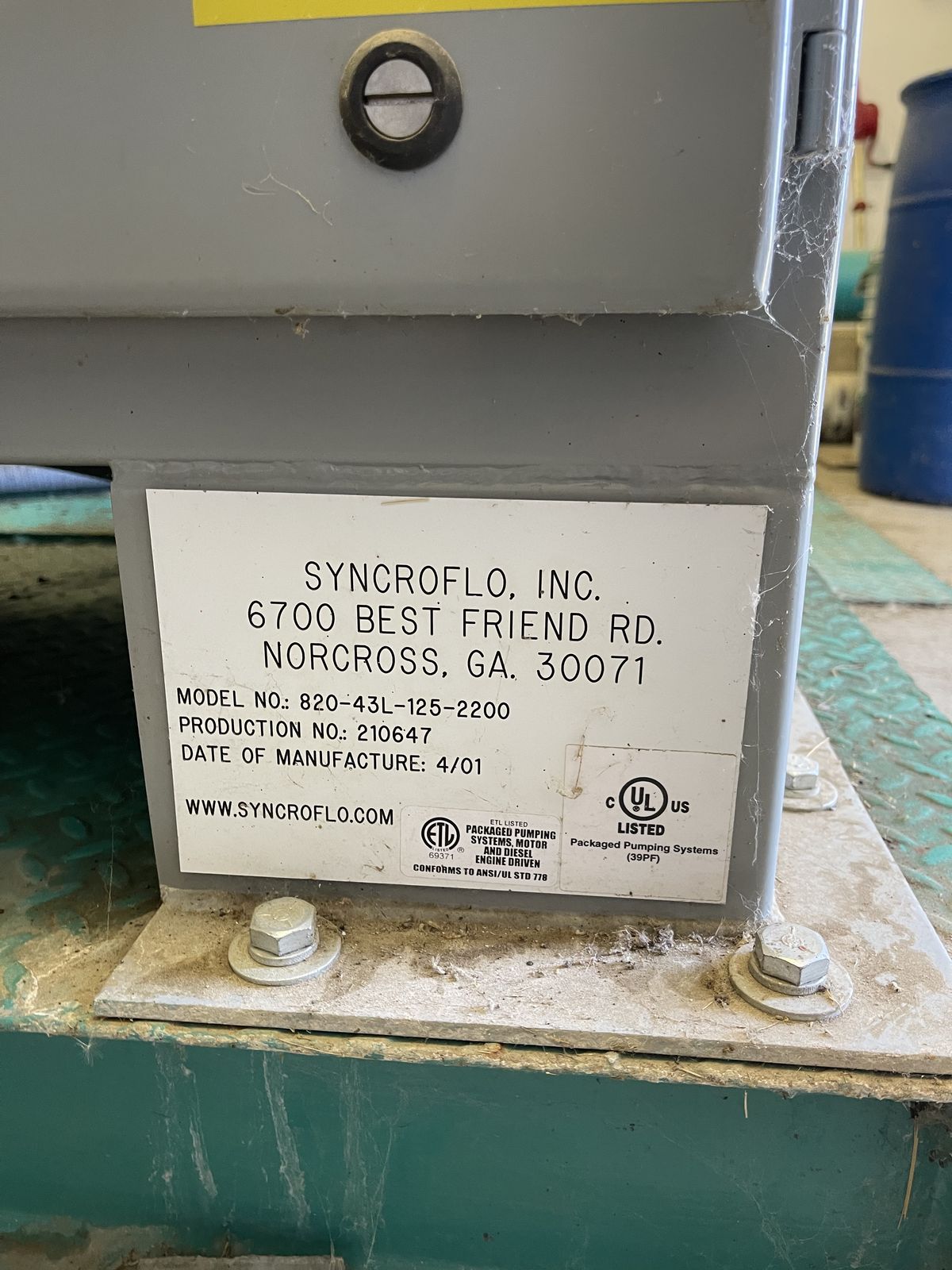
The irrigation pump station at Bootleg Gap Golf in Kimberley, BC is a SyncroFlo built in April 2001. In the 2026 season we replaced its PLC, its operator screen and its drive inside the original cabinet. This is the record of that job.
| Course | Bootleg Gap Golf, Kimberley, BC |
|---|---|
| Station | SyncroFlo packaged pump station, Model 820-43L-125-2200, built April 2001 |
| Operator's guide | Titled VFD-Eagle (EagleEye version) Irrigation Pumping Station Operator's Guide. The 820 at the front of the model number matches SyncroFlo's 820 Series VFD-Eagle. |
| Pumps | Three turbine pumps, one pressure maintenance pump and one transfer pump that tops up the pond |
| Drive | One variable frequency drive, shared. The lead turbine runs on the drive. The other two come on at full voltage when the drive is at full speed. |
| What was there | A Mitsubishi FX2N-32MR PLC, a small keypad with a text display on the door and a Toshiba E3 drive |
| What went in | A Siemens S7-1200 PLC, a 7 inch Siemens touch screen and a Franklin Electric Cerus X-Drive |
| When | The 2026 season. The old PLC came out after 31 March 2026, and the station was watering on the new controls in June 2026. |
The model number and the build date are from the nameplate. The photos of the station open full size if you want to read the labels.
What was wrong
The station has one variable frequency drive and all three turbines share it. That drive was a Toshiba E3, and it died at the start of the 2026 season.
The PLC was a Mitsubishi FX2N-32MR. Mitsubishi stopped making the FX2N in 2012 and ended factory repair in 2019. Those dates are from Mitsubishi Electric's own legacy product page.
The station was built in April 2001, so by 2026 it was 25 years old.
We are independent. Controler and Oler Industries are not affiliated with SyncroFlo, Inc., which is still in business in Norcross, Georgia.
What we did
We did the install ourselves. The cabinet, the pumps and the piping stayed.
Scope of work
- Replaced the PLC and rewired the controls
- Wrote a new PLC program
- Replaced the operator screen
- Replaced the drive
- Replaced the pressure sensor
- Replaced the level sensor
- Added high and low floats in the sump
What we kept
- The SyncroFlo cabinet and backplate
- The field terminal strips
- The pump contactors and overloads
- The hour meters on the door
- The pumps
- The piping
The new gear
Every wire is labelled. We wrote the PLC program ourselves and tuned the pressure loop at the station.
- Siemens S7-1200 PLC, CPU 1215C with three expansion modules
- Siemens Scalance network switch
- Finder interface relays
- 7 inch Siemens touch screen
- Franklin Electric Cerus X-Drive, with its keypad on the door

Before and after
The before photos were taken in August 2023 and March 2026. The after photos were taken in June 2026.
The cabinet door
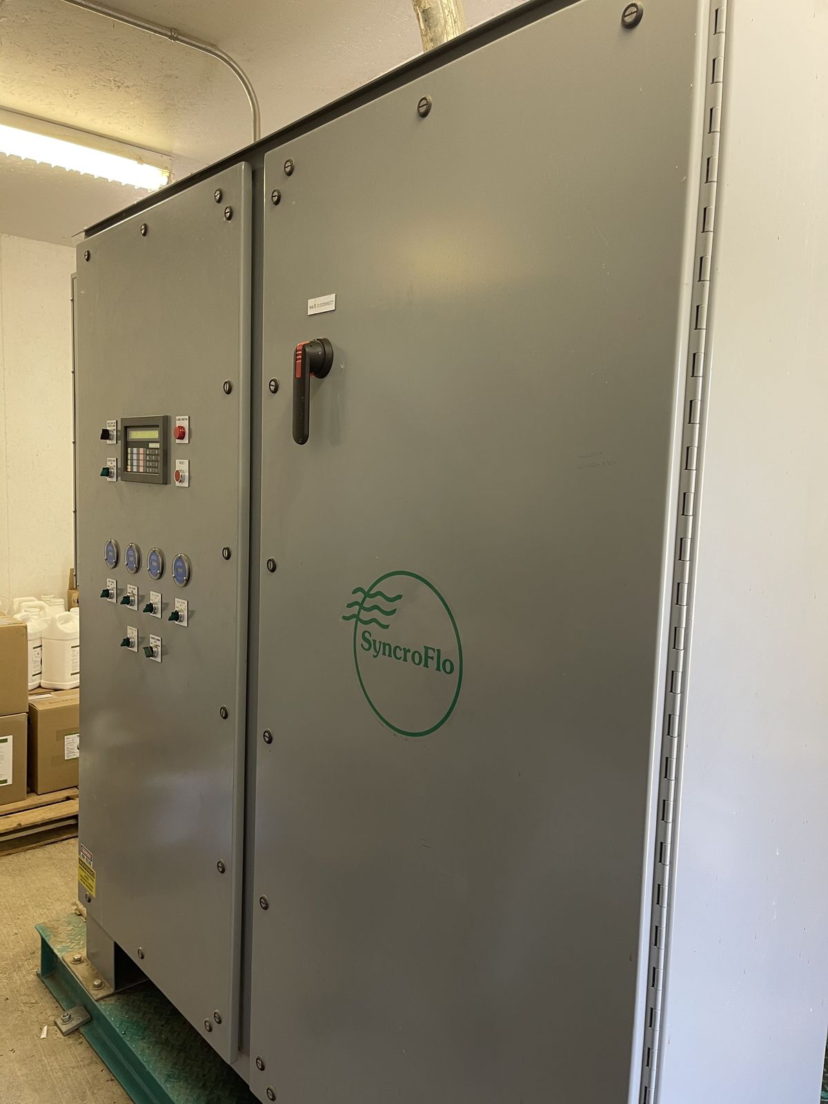
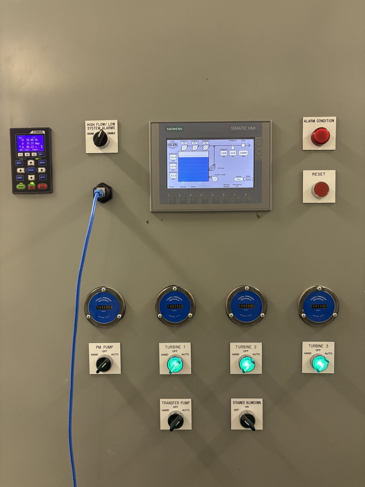
The door used to have a small keypad with a text display. Now it has a 7 inch Siemens touch screen and the drive keypad. It still has an alarm light, a reset button, a Hand-Off-Auto switch for each pump and a strainer blowdown switch. The four hour meters are the originals.
The PLC and the wiring
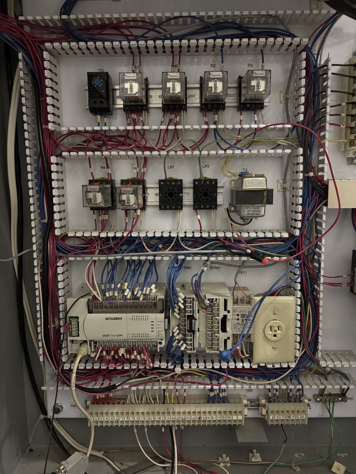
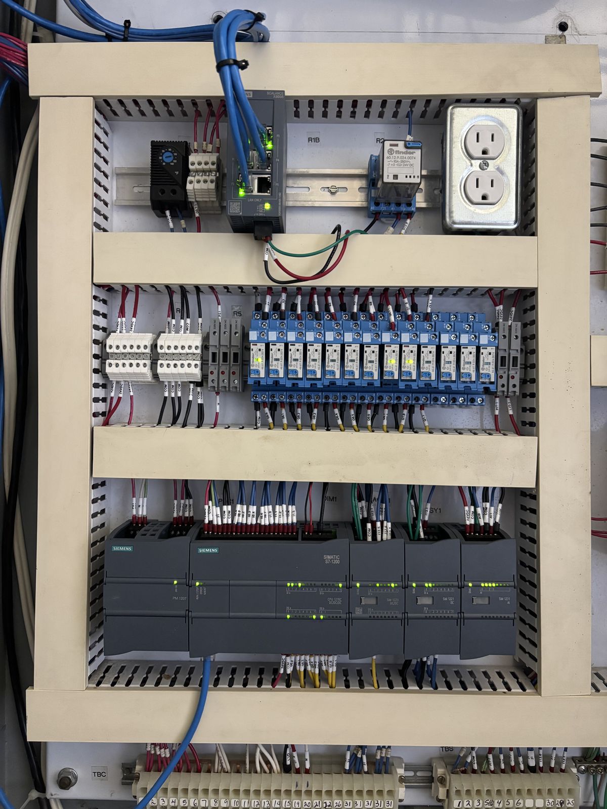
A Mitsubishi FX2N-32MR came out. A Siemens S7-1200 (CPU 1215C with three expansion modules) went in on the same backplate, with Finder interface relays and a Siemens Scalance network switch. We rewired the controls and labelled every wire.
Look along the bottom of both photos. The terminal strips marked TBC and TBS are the same ones. Those are the field terminal strips, and we kept them.
The drive
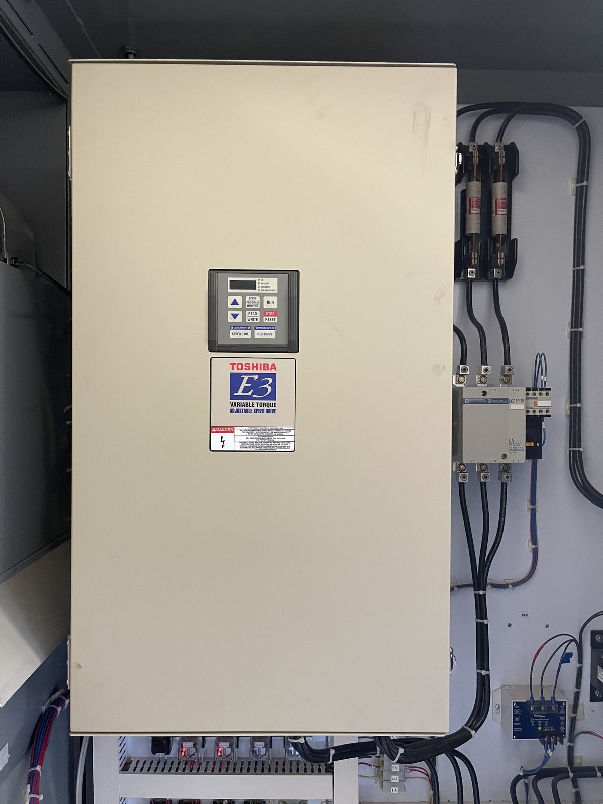
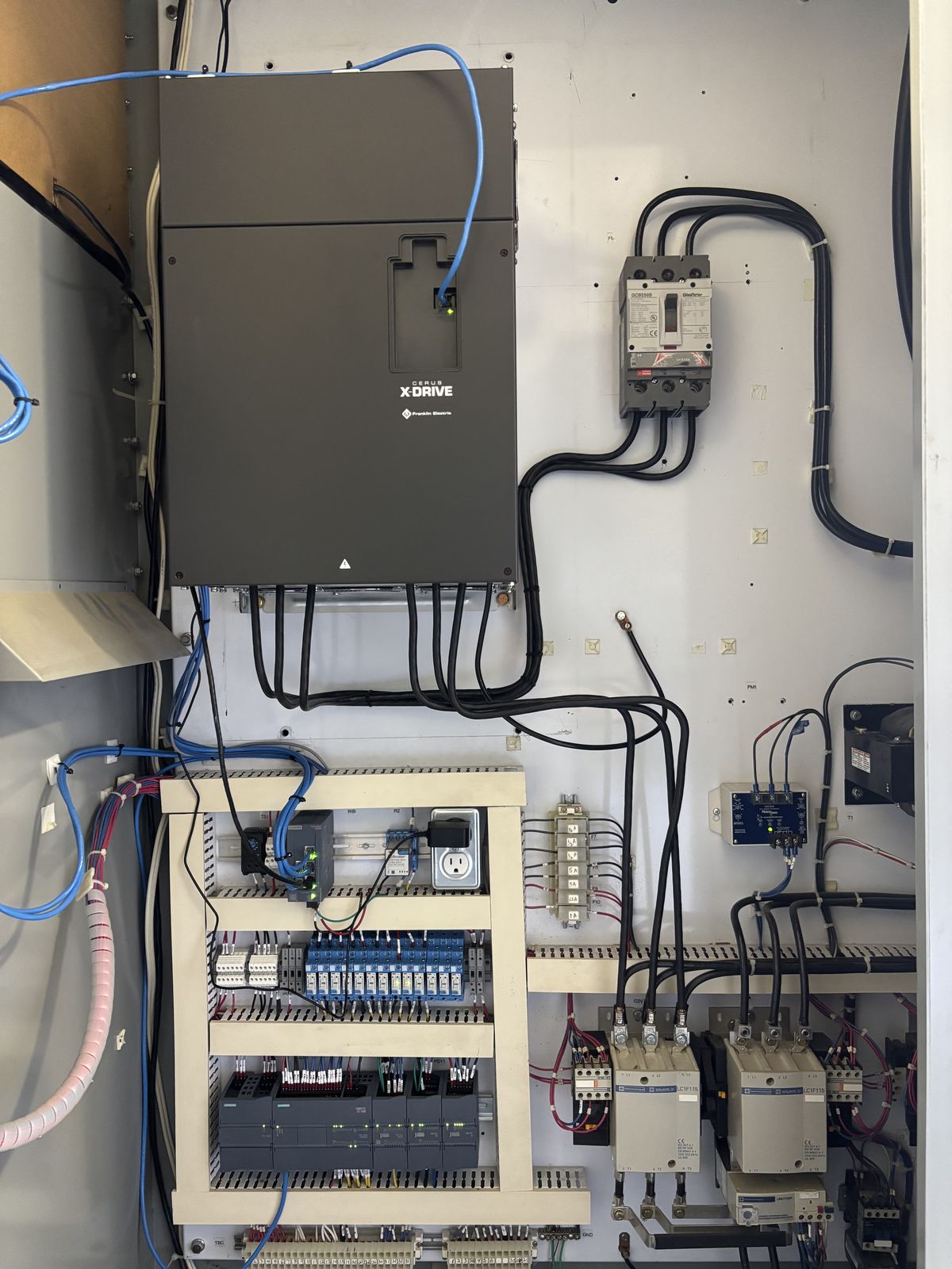
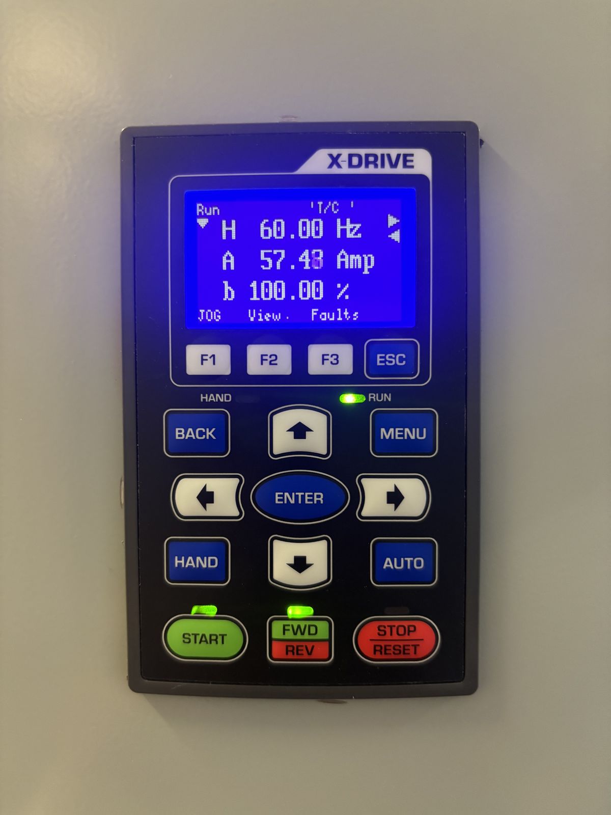
The old drive was a Toshiba E3. The new one is a Franklin Electric Cerus X-Drive, mounted where the Toshiba was. Its keypad is out on the door.
How it runs now
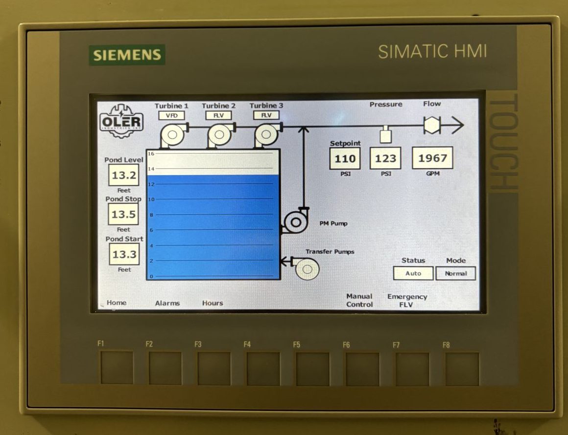
Both photos were taken at Bootleg Gap in June 2026 with the pumps running.
In automatic
The operator sets one pressure setpoint. The PLC decides which pumps run.
| Lead turbine | The station picks the turbine with the lowest hours and runs it on the drive. |
|---|---|
| More demand | When the drive is at full speed and pressure is still low, the station brings on the other turbines at full voltage, one at a time. |
| Nobody watering | The pressure maintenance pump holds pressure. |
| Pond | The transfer pump keeps the pond between a start level and a stop level. |
| Alarms | High and low pressure, high and low flow, pump overloads, phase loss and drive fault. An alarm latches and stops the pumps until someone resets it. |
| Other screen pages | Alarms, pump hours, manual control and an emergency full voltage page. |
The emergency full voltage page
You can see its name, Emergency FLV, along the bottom of the touch screen in the photo above. FLV is short for full voltage.
The station has one drive. If that drive is ever out, the operator can turn on an emergency mode on this page and run the turbines at full voltage from the screen.
In emergency mode
- The drive is locked out.
- The alarms stay live.
- Each pump's switch still has to be in Auto.
- Pressure control is by hand.
Remote monitoring
Since June 2026 the station has been logged over a cellular link on a private encrypted connection. We can see pressure, flow, pump status and alarms from the shop.
Have a SyncroFlo station of your own?
If the tag on your station looks like the one at the top of this page, we have already done one. If yours is a different model or year, email us a photo of the tag.
How the SyncroFlo control retrofit works
Book a free pump station review or call Warren at 250-581-2225