
SyncroFlo Eagle alarms in plain words
What the alarm messages on a SyncroFlo Eagle irrigation pump station mean, what the station does when each one trips, and what to check first.
Which stations this covers
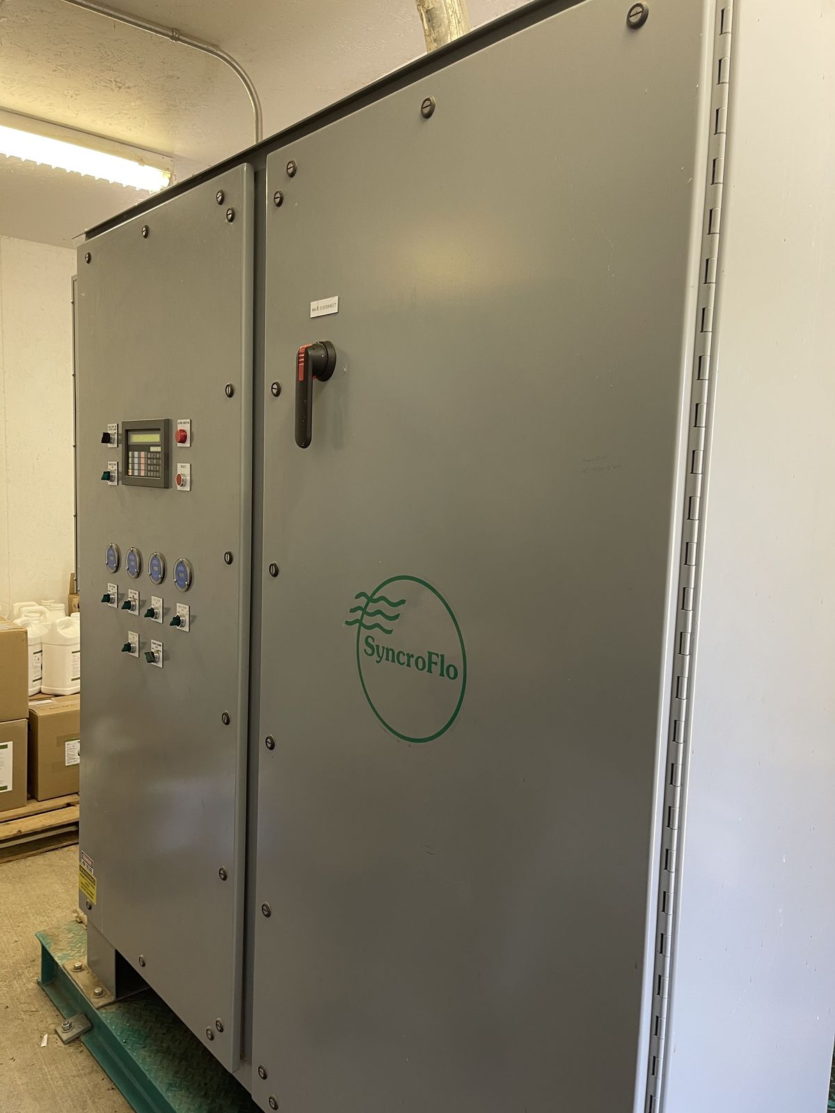
SyncroFlo Eagle golf course irrigation pump stations with the EagleEye keypad and text display on the door.
We wrote this from the operator's guide for the pump station at Bootleg Gap Golf in Kimberley, BC. That station is a SyncroFlo Model 820-43L-125-2200, built in April 2001.
The guide is titled "VFD-Eagle (EagleEye version) Irrigation Pumping Station Operator's Guide". Our copy is dated August 1997. This page is our own reading of it, in our own words. It is not a factory document.
Stations differ, and so do editions of the guide. Some of these alarms are only fitted on some stations, and the pressure and flow settings are set for each course. The times and numbers on this page are the ones printed in our copy.
Your own station's guide comes first. Everything under "You can check" is done with the panel doors shut. Anything inside the panel is for an electrician. Work on the pumps, the valves and the piping is for a pump tech. Switching the main disconnect off unlatches the panel doors. Leave them shut.
Two words the guide uses. It calls the drive "the inverter". It calls the keypad and display "the OIT".
When the alarm light is on
Before you press Reset, write down what the station is telling you. It takes two minutes, and it is the first thing the person fixing it will ask for.
Write down
- The exact words on the display
- The date and the time
- The pressure and flow on the display (PSI and GPM)
- The pressure on a gauge, if the station has one
- Which pumps are running. Each pump switch has a run light in its handle.
- Whether the alarm light is steady or flashing
Before you reset
Take a photo of the display.
Have a look around the pump house and, for a pressure or flow alarm, out on the course.
Reset puts the station back into automatic, so pumps can start. Make sure nobody is working on the pumps, the pump house piping or the irrigation pipe out on the course.
An alarm is not a lockout. The power failure, irregular power, PLC failure and PLC input failure alarms clear themselves, and the pumps can start with nobody at the door. Before anyone puts a hand on a pump, a motor or the pipe, have the station locked out.
If you reset and the same alarm comes back, stop there. Find the cause before you reset it again.
If the alarm light stays on after a reset, the fault is still there. The Alarm List key shows which alarm it is.
What the door tells you
Looking is safe. The guide says the screen keys (Status, Mode, Alarm List and the others with coloured labels) cannot change how the station runs when pressed by themselves.
Changes are made with the Toggle, Clear, Enter, plus, minus and number keys. Leave those alone unless you know what they will do on the screen you are on.
| Alarm light on steady | An alarm is active now. |
|---|---|
| Alarm light flashing | An alarm tripped earlier and reset itself. The light keeps flashing until someone presses Reset. |
| Status screen | "ALL OK" at the end of the top line means no alarms. A flashing "ALARM!" on the bottom line means one is active. If the two take turns, an alarm tripped and reset itself. |
| An alarm message on the display | Write it down, then press the Alarm Ack key to clear it off the display. The station holds up to 10 messages, so you may have to press it more than once. Alarm Ack clears the message, not the alarm. Resetting is done with the red Reset button. |
| "Alarm in Progress!!!" | You pressed one of the screen keys while an alarm message was showing. Press Alarm Ack first. |
| Alarm List key | Goes through the alarms, one screen each, and shows whether each one is on or off. Use the Page Down key to step through them. Display failure is the one alarm that is not in the list. |
| Last Alarm key | A snapshot of the moment the last alarm tripped: its code, the date and time, GPM, PSI and the set point (SP). The pump code shows which pumps were running, so 02300 means pumps 2 and 3. The mode code is two letters. The first is V or C, for variable or constant speed. The second is N, E, R or L, for normal, energy, refill or lockout. |
| Alarm History key | The last 200 events, newest first. It also records resets. SR is a reset after the whole station was shut down. AR is a reset of any other alarm. |
| Alarm Lt. Test key | Tests the alarm light. Press and hold it and the light should come on. The same screen shows whether the light is meant to be on or off right now. |
| Words scrolling across the top line | The screen saver. It starts after 30 minutes with no key pressed. Press any key to get the display back. |
| "Enter Setup Password:" | Someone pressed the Setup key. The guide says that key is for factory programming. Press Clear to go back. |
Find your alarm
An alarm message names the alarm in capital letters and gives its code, for example "HIGH FLOW RATE ALARM (CODE HF)". The Last Alarm and Alarm History screens show the code and not the name.
Motor and pump alarms carry the number of the motor or pump. Each of those stops one pump and leaves the rest running.
These shut the station down
- High flow rate (HF)
- High system pressure (HS)
- Irregular power (IP)
- Low level (LL)
- Low system pressure (LS)
- PLC failure (PC)
- PLC input failure (PI)
- Power failure (PF)
- Pressure transducer failure (PT)
These leave the station running
- Contactor fault (C and the motor number)
- Display failure (DF)
- Flow sensor failure (FS)
- High panel temperature (HT)
- Inverter contactor fault (IC)
- Inverter failure (IF)
- Inverter trip (IT)
- Jobsite settings lost (JS)
- Motor overload (O and the motor number)
- PLC low battery (LB)
- Pump failure (F and the pump number)
Pressure alarms
The station reads system pressure from a sensor inside the panel. The guide calls it the pressure transducer.
Low system pressure (code LS)
Pressure has stayed below the low pressure setting for 5 minutes. While the station is refilling the pipe in refill mode, the guide allows 15 minutes.
The station shuts down and stays off until someone presses Reset. It will reset even if the pressure is still low. This alarm only works with the alarm switch on Enabled, and it is off during lockout mode.
You can check
- Before you reset, press the Mode key. If VFD shows off, the drive is locked out and there is no refill mode. A reset will start a main pump at full voltage into a pipe that has lost its pressure. Call your pump tech or us before you reset.
- Water on the course. A large break in the irrigation piping is on the guide's list.
- Too many sprinklers on at once for what the station can pump
- A pump switch left on Off
- Another alarm on one of the pumps: overload, contactor fault or pump failure
- Manual speed left on. The Speed Control key shows it.
- A pump isolation valve closed. If you do not know why it is shut, ask before you open it.
- The water supply to the pumps, low or restricted
For an electrician or pump tech
- The relief valve stuck open or set too low, or the small valves and strainer on its pilot piping
- The pressure transducer, or its sensing line shut off
- A failed motor, a motor running backwards, blown fuses or a tripped breaker
- A check valve installed backwards
- The low pressure alarm setting
High system pressure (code HS)
Pressure has stayed above the high pressure setting for 1 minute.
The station shuts down and stays off until someone presses Reset. It will not reset while the pressure is still above the setting.
You can check
- The pressure now, on the display and on a gauge. If it is still high, Reset will not work yet.
- The valves at the relief valve. The guide lists a closed inlet valve and closed ball valves on the pilot piping as causes. If one is shut and you do not know why, ask before you open it.
For an electrician or pump tech
- The relief valve set too high, or failed
- The pressure transducer sensing line shut off
- The high pressure alarm setting set too low
Pressure transducer failure (code PT)
The pressure reading has been out of range, below 0 or above 225 PSI, for 30 seconds. The PLC takes that to mean the sensor or its wiring has failed.
The station shuts down. The guide warns that this alarm cannot catch every failure. A sensor stuck at a believable number, which can happen after freeze damage, will not trip it.
You can check
- PSI on the display against a gauge on the piping, if there is one. Write both down.
- Whether the pump house could have frozen
For an electrician or pump tech
- Loose or broken wiring, or a short circuit
- The pull-up resistor on the signal
- The input terminal strip on the PLC
- The transducer itself, failed or frozen
- The 24 volt DC power supply
Flow alarms
Flow is read by a flow sensor on the discharge manifold.
High flow rate (code HF)
Flow has stayed above the high flow setting for 5 minutes. The guide ties this alarm, and the low pressure one, to the risk of a large break in the irrigation piping.
The station shuts down and stays off until someone presses Reset. It can always be reset, because the flow is gone once the pumps stop. This alarm only works with the alarm switch on Enabled, and it is off during refill mode.
You can check
- Water on the course. Look for a break before you reset, not after.
- Too many sprinklers on at once
- A main pump switched off, or stopped by an alarm of its own. The guide lists both as causes.
For an electrician or pump tech
- The flow sensor failed or reading high
- The high flow settings set too low
Flow sensor failure (code FS)
The first main pump has started automatically 10 times in a row and the flow reading never came off zero. The guide says this alarm only catches a sensor that has failed completely.
The station keeps running. It switches to what the guide calls back-up pressure operation, where pressure is also used to stop main pumps that are running at full speed.
The guide adds that main pumps shutting off at the wrong time, with large pressure swings, point to a flow sensor that has failed or reads wrong. Its stopgap is to run the main pumps in Hand, with someone at the station, until the sensor is repaired. In Hand the pressure alarms still work, but the high flow alarm cannot see a break through a dead flow sensor, and nothing starts or stops the pumps for you. Talk to your pump tech before you water that way.
You can check
- GPM on the Status screen while sprinklers are running. If it reads zero while water is going out, the reading is wrong.
- Main pumps shutting off at odd times, or pressure swinging up and down
For an electrician or pump tech
- Loose or broken wiring, or a short circuit
- The pull-up resistor on the signal
- The input terminal strip on the PLC
- The flow sensor itself
Water level and supply
These two are about the pumps running out of water. Not every station has them.
Low level (code LL)
Only on stations with vertical turbine pumps set in a wet well. The level probes in the wet well have shown low water for 10 seconds.
The station shuts down. Reset will not work until the water is 6 inches or more above the level where the alarm trips.
You can check
- The level in the pond or lake
- The inlet screen and the supply pipe, as far as you can see them from outside. A clogged screen and a shut-off supply are both on the guide's list.
- Look from the top. Do not go into the wet well.
For an electrician or pump tech
- Level probes that are damaged, dirty, corroded or the wrong length
- Probe wires loose or connected wrong
- The level relay in the panel
- Ground continuity between the station and the wet well
Pump failure (code F and a number)
An optional alarm. The code is the letter F and the pump number. The guide says it is typically used with centrifugal pumps, to protect them if they lose their water. A pump was meant to be running and its pressure switch has shown very low discharge pressure for 10 seconds.
That pump stops and stays off. The other pumps take over and the rest of the station keeps running. It can always be reset, so find out why it tripped before you do.
You can check
- The water supply: the pond level, and whether the supply pipe is clogged or shut off
- The suction valve on that pump
- Whether the course was asking for more water than the supply can give
For an electrician or pump tech
- The pump failure pressure switch: its setting, its sensing line and its wiring
- A failed pump or motor, or a motor running backwards
- Blown motor fuses or a tripped breaker
- An obstruction in the pump
Motors and power
The two power alarms reset themselves, and the alarm light flashes afterwards until someone presses Reset. The two motor alarms take one pump out and leave the rest of the station running.
Power failure (code PF)
Power to the station was off and has come back. By itself it does not mean anything in the station has failed. It keeps the pumps from starting the instant the power returns, so you will also see it after the station power has been switched off and on again.
The station stays off. Once the power has been on for 30 seconds without a break, the alarm resets itself and the station is allowed to run. It can also be reset by hand.
You can check
- When it happened. The Last Alarm and Alarm History keys show the time.
- Whether it keeps happening
For an electrician or pump tech
- The incoming power, if this alarm keeps coming back
Irregular power (code IP)
A power monitor inside the panel has seen something wrong on the incoming power. The guide lists voltage under 90 percent of normal, a lost phase, a reversed phase and phases out of balance.
The station shuts down at once. When the power has been normal for 30 seconds, the alarm resets itself and the station is allowed to run. It can also be reset by hand.
You can check
- When it happened, from the Last Alarm and Alarm History keys
- Whether the power dipped or went out anywhere else on the property at that time
- Whether it keeps happening
For an electrician or pump tech
- Line voltage and the phases at the station
- The power monitor: its voltage adjustment, its fuses and the monitor itself
- Incoming power lines not connected in phase with the station
Motor overload (code O and a number)
The overload relay on that motor's starter has tripped. The code is the letter O and the motor number.
That pump stops at once and stays off. The other pumps take over and the rest of the station keeps running.
On some of the larger starters, the guide says the overload relay has to be reset by hand inside the panel before the alarm will reset. That is an electrician's job.
You can check
- Which motor it is, from the number in the message
- Whether the station was at very high flow when it tripped
- Whether air can move freely around the motor
- The guide's advice for a pump with something wrong is to turn its switch to Off and let the others carry on. Do not keep resetting an overload.
For an electrician or pump tech
- The motor drawing too much current, or voltage that is low or high
- A blown motor fuse or a loose power wire, which leaves the motor on a single phase
- A fault in the motor
- The overload relay itself
Contactor fault (code C and a number)
A motor contactor is not where the PLC told it to be. It is open when it should be closed, or closed when it should be open, and has been for 2 seconds. The code is the letter C and the motor number.
That pump is shut down and stays off. The exception is a contactor that is stuck closed, where the pump keeps running. The other pumps take over and the rest of the station keeps running.
The guide says a contactor fault that refuses to reset means the contactor needs replacing without delay. A main pump motor has two contactors, and the alarm does not tell you which of the two it is.
You can check
- Whether that pump is running when it should be off. Look and listen at the pump, and look at the run light in its switch handle.
- If a pump will not stop with its switch on Off, call an electrician. If it has to be stopped now, the main disconnect handle on the door shuts off power to the pumps. Turning it off also unlatches the panel doors. Leave them shut. The incoming power is still live inside.
For an electrician or pump tech
- A loose wire on the contactor or the PLC
- The contactor coil or its auxiliary contact
- A contactor stuck open or stuck closed
- The mechanical interlock
- The overload relay
- A PLC input or output
Drive alarms
The guide calls the drive the inverter. The three inverter alarms all end the same way. The drive shuts down, the pump it was running goes to full voltage, and the station carries on at constant speed.
Inverter trip (code IT)
The drive has tripped on a fault of its own and signalled the PLC.
The drive shuts down. Its pump switches straight to full voltage and the station runs at constant speed. The PLC then tries to reset the drive every 30 seconds. If a reset works, the PLC stops that pump and lets the drive run it again.
If the fault is still there after 2 tries, or 3 faults happen inside 15 minutes, the PLC keeps the drive locked out. The alarm can also be reset by hand.
You can check
- The Mode key. VFD shows on when the drive is available and off when it is not.
- The inverter mode switch on the door. Auto is the normal position. If it is on Off or Test and you do not know why, ask before you move it. The guide says not to turn it to Test or Off while the drive is running a main pump.
- Whether the Alarm History shows an irregular power alarm at about the same time
For an electrician or pump tech
- The fault shown on the drive itself, and the drive's own manual
- Too much current, or too little voltage, at the drive
- The drive's deceleration setting
- The guide recommends testing the drive after any lockout, with the inverter mode switch on Test. That runs the drive without a pump.
Inverter failure (code IF)
A back-up check, for problems the drive cannot report by itself. The PLC was asking for full speed, the pressure was below the low pressure setting, and for 60 seconds the drive never signalled that it had reached full speed.
The drive is locked out, its pump goes to full voltage and the station runs at constant speed. The alarm can always be reset.
You can check
- The Mode key, to see whether the drive is available
- Whether it comes back after one reset. If it does, it needs a repair.
For an electrician or pump tech
- A loose wire on the PLC or the drive
- The drive's maximum speed setting
- Blown drive fuses
- The drive's control board
- The PLC analog output module, failed or out of calibration
- A PLC input module
Inverter contactor fault (code IC)
The line contactor for the drive is not where the PLC told it to be, and has not been for 5 seconds.
The drive is locked out, its pump goes to full voltage and the station runs at constant speed. The guide says that if it refuses to reset, the drive's line contactor needs replacing without delay.
You can check
- Whether it clears with one reset. If it will not reset, call an electrician.
For an electrician or pump tech
- A loose wire on the contactor or the PLC
- The contactor coil or its auxiliary contact
- The contactor stuck open or stuck closed
- A PLC input or output
High panel temperature (code HT)
The thermostat inside the control panel has read high for 30 minutes. The cooling unit on the side of the cabinet is there to keep the panel under 104 degrees Fahrenheit (40 Celsius) and protect the drive.
Nothing else happens. The station keeps running. The alarm resets itself once the panel has cooled 10 degrees below the thermostat setting. It can also be reset by hand.
You can check
- Whether the cooling unit on the side of the cabinet is running
- If the cooler is the kind that uses irrigation water, the ball valve on its water line. The guide says it should be fully open.
- How hot the pump house is
- Do not prop the panel doors open to cool it.
For an electrician or pump tech
- The thermostat setting, or where the thermostat is mounted
- The heat exchanger failed, or its water flow set too low
- The air conditioner failed, or its thermostat set too high
Controller and display
The controller is the PLC inside the panel. The display is the EagleEye keypad on the door.
Jobsite settings lost (code JS)
The PLC found its stored settings gone and loaded the factory settings back in by itself.
The station keeps running, but on the factory settings and not the ones set for your course. The set point and the alarm limits may now be wrong for your pipe. Get your own settings put back in before the next night of watering.
This alarm is reset from its own screen in the Alarm List, with the Toggle key. If it happens after a power failure, no alarm message comes up. The Alarm List is where you will find it.
You can check
- The settings on the display against the jobsite settings written in your copy of the guide. The guide has blanks for writing them in. While you look, use only the menu numbers and the Page Up and Page Down keys.
- Whether a PLC low battery alarm is on as well
For an electrician or pump tech
- The PLC battery
- A CPU module that has just been installed
- A heavy power surge or an electrical fault
- A fault in the CPU memory
- Putting the jobsite settings back in
PLC failure (code PC)
The PLC has stopped running.
The station shuts down. The alarm light, the word "ALARM!" on the Status screen and the alarm message will probably not work, because the PLC is what runs them. The guide says the Alarm List is usually the only place this alarm shows. It clears by itself once the PLC is running again.
The guide says a bypass circuit lets the pumps be run in Hand while the PLC is stopped. It also says the drive, the pump sequencing and the alarms do not work then. With the PLC stopped, a pump in Hand starts at full voltage and nothing shuts it down for low water, high pressure or a break. Do not run pumps that way unless your electrician or pump tech is at the station.
You can check
- The Alarm List, to see whether PLC failure is on
- The guide's first step is to switch the station power off for 15 seconds and then back on. Turn every pump switch to Off first. The guide gives Off as the position for restarting the station. If the Alarm List then shows PLC failure is off, put the switches back to Auto. If the alarm is still on, leave the switches on Off and call.
For an electrician or pump tech
- The error number on this alarm's screen in the Alarm List. The guide says it is a CPU diagnostic code.
- A PLC hardware failure
- A heavy power surge or an electrical fault
- The PLC left in programming mode
PLC low battery (code LB)
The battery in the PLC is low. The guide says that battery runs the clock and keeps the stored data while the power is off, and that it does not hold the program.
Nothing else happens and the station keeps running. The guide says there is a 30 day reserve after the alarm comes on, and to replace the battery as soon as possible. The alarm clears by itself once the battery voltage is back to normal.
You can check
- That your jobsite settings are written down while the PLC still has them
- Get the battery changed before the station is switched off for the winter. With the power off, the battery is all that holds the settings.
- When the alarm first came on, from the Alarm History key
For an electrician or pump tech
- A battery near the end of its life
- A battery that has come unplugged
- A CPU fault
PLC input failure (code PI)
The PLC inputs have been without power for 60 seconds. Without input power the PLC cannot control the station at all.
The station shuts down. The alarm clears by itself once input power is back.
You can check
- The Reset button. The guide lists a Reset button that is held in or broken as a cause.
For an electrician or pump tech
- A loose wire or a short circuit
- The 24 volt DC power supply
- The Reset button itself
Display failure (code DF)
The PLC has lost contact with the keypad and display for 30 seconds. There is no message screen for this one. The alarm light comes on. The guide gives it the code DF and says it does not appear in the Alarm List.
The station keeps running in automatic. The PLC turns off manual speed, clock setting and inverter setup mode if any of them were on. The alarm clears by itself once the display and the PLC are talking again.
You can check
- Whether the display is blank, frozen or not answering its keys
- The guide says the Clear key can reset the display after communication has been interrupted.
- The guide's step for this alarm is to switch the station power off for 15 seconds and then back on. Pick a time when no pumps are running and no pump switch is on Hand. If the alarm comes back within a minute, it needs a repair.
For an electrician or pump tech
- The communication cable plug at the display or at the PLC
- Electrical noise
- The 24 volt DC power supply
Things that trip people up
Each of these is in the guide. They are easy to miss when you are standing at the door.
-
The alarm switch left on Disabled
The door has a switch for the high flow and low system pressure alarms. On Disabled, neither alarm can shut the station down.
The guide says that position is for filling the pipe at start-up, or while a pump is down for service, and that the station has to be checked often while it is there. Those two are the alarms the guide ties to a broken main, so in the meantime the only one watching for a break is you.
Enabled is the normal position. Put the switch back there as soon as the fill or the repair is done.
-
One pump running slowly after a reset
That is refill mode. It comes on when a main pump starts after a shutdown and the pressure is far below the normal set point. The guide's figure is 50 PSI below.
Only the main pump on the drive runs. It brings the pressure up a few PSI at a time until it is close to the set point, then the station goes back to normal. During the refill the high flow alarm is off and the low pressure alarm waits 15 minutes.
The Mode key shows whether refill is on. The guide says refill mode needs the drive. With the drive locked out there is no refill mode. If the pipe has lost its pressure and the drive is locked out, do not reset. Call first.
-
A pump switch left on Hand
Hand is for a short manual run or a test. The automatic starting and stopping is bypassed, so the guide says someone should be at the station while a pump is in Hand.
The guide says the alarms still protect the pumps and the pipe in Hand, as long as the PLC is running. Auto is the normal position.
-
A drive alarm does not stop the station
When one of its alarms locks the drive out, the station drops to constant speed. Main pumps start at full voltage as they are needed and the relief valve limits the pressure.
The guide says the station still delivers its pressure and flow that way. What is lost is the soft start and the speed control. The alarm light and the Mode key are how you tell.
-
What the PLC battery keeps
The guide says it runs the clock and keeps the stored data while the power is off. It does not hold the program.
If the settings are lost, the PLC loads the factory settings and carries on. A failed battery is one of the causes the guide lists for that. Keep your own settings written in the guide.
-
What the relief valve is for
It limits the station's discharge pressure whenever a main pump is running at full voltage. It also takes the shock when the flow stops suddenly, as in a power failure.
The guide lists it as a possible cause of both the low and the high pressure alarms. The guide says setting it takes some trial and error. That is work for a pump tech.
-
What else the Reset button does
A press is all it takes to reset an alarm. The guide says that holding the button in for a minute shuts the station down until it is let go. It uses that as a test of the PLC input failure alarm.
A press also ends the minimum run timers. Pumps that are no longer needed can then stop, once their stop delays have run out.
-
Main pumps that will not start, with no alarm
Check the Mode key. Lockout mode keeps every main pump from running between set hours of the day, in Hand as well as in Auto. It is a setting, not an alarm.
-
Alarm times that look wrong
The guide says the clock does not change itself for daylight saving time, so the times on the alarm screens can be an hour out.
It also says the alarm history does not work while the clock is stopped. The clock stops if "set clock" is left on in the settings.
When the controls are the problem
Sometimes the fix is one sensor or one setting. Sometimes it is the controls themselves.
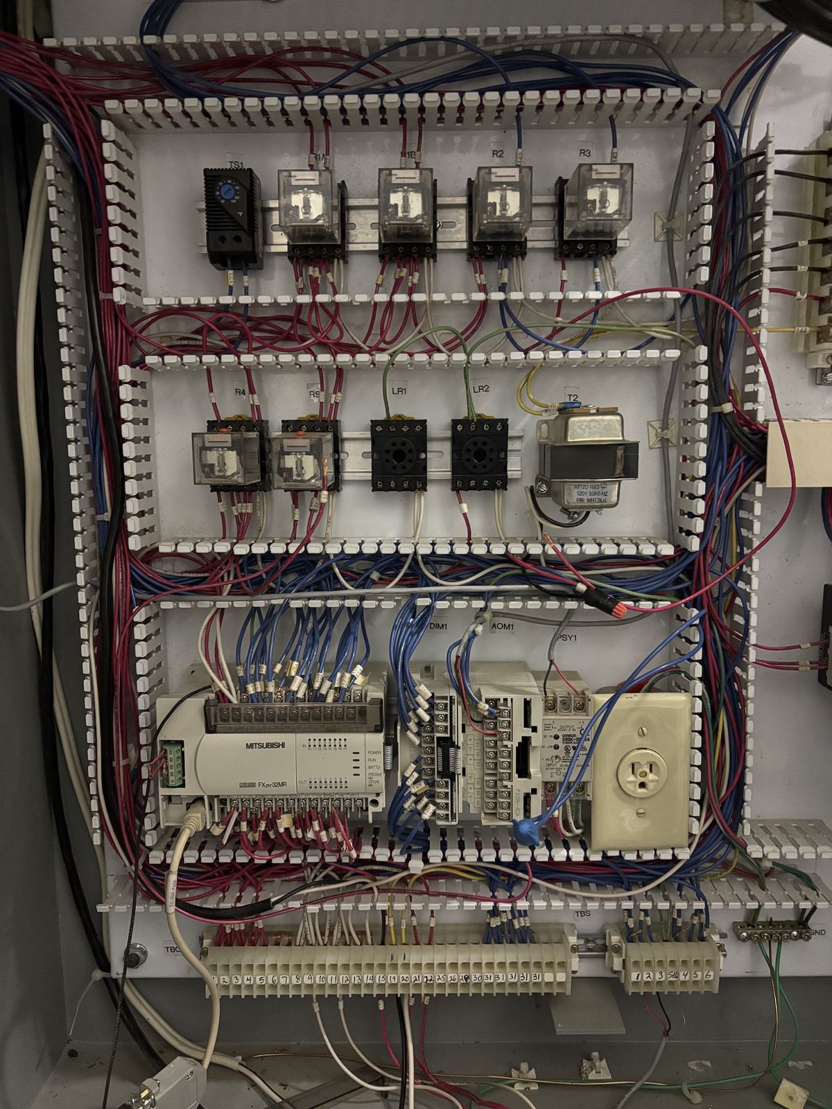
The old PLC in the Bootleg Gap station was a Mitsubishi FX2N-32MR. Mitsubishi stopped making the FX2N in 2012 and ended factory repair in 2019.
If the controls are too old to be worth fixing, we replace them and keep the cabinet, the pumps and the piping.
How the SyncroFlo control retrofit works
Read the full Bootleg Gap write-up
We are independent. Controler and Oler Industries are not affiliated with SyncroFlo, Inc., which is still in business in Norcross, Georgia.
This page is our own summary, in our own words. It does not replace the operator's guide for your station, or the factory's advice.
Same alarm keeps coming back?
Tell us what the display says and what the station is doing. We will get back to you. If you are within about three and a half hours of Cranbrook, we will set up a time to come and look at it.
Book a free pump station review or call Warren at 250-581-2225
Other guides: Irrigation software vs. pump station controls and Pump station spring start-up checklist.